DESIGN GUIDE
RALPH KITTLER, P. ENG.

The creation of this Natatorium Design Guide has been a collaboration between the sales, service, and engineering teams of three of the industry’s most respected dehumidifier brands, led by Ralph Kittler. Quite simply, nobody in the industry has better credentials than Ralph to create all of our natatorium design educational materials.
In addition to being a founding partner of Seresco, he is also currently chairman of the CDC’s Council for the Model Aquatic Health Code (CMAHC) ad hoc committee on indoor air quality. The committee’s mandate is to identify and assess the factors affecting air quality at indoor aquatic facilities and develop revisions to the Model Aquatic Health Code (MAHC) to better address ventilation/air quality design and operational criteria.
Ralph was an ASHRAE “Distinguished Lecturer” on indoor pool design for 12 years and sits on two technical committees: TC 8.10 “Mechanical Dehumidifiers and Related Equipment” and TC 9.8 “Large Building Air Conditioning Applications.” He is the primary revisor on two ASHRAE Handbook chapters and helped create the new “Indoor Pool Design” chapter (Applications 2019 Chapter 25).
Chapter ONE
The know-how and experience to provide a first-class indoor pool experience exists today. There are hundreds of successful indoor pools currently operating in North America.
Resources are available to help guide and educate indoor pool designers, operators, and owners. In 2019, ASHRAE created a new chapter in the design handbooks dedicated to indoor pool design. The CDC’s Council for the Model Aquatic Health Code (CMAHC) is also actively working to provide better guidelines on indoor pool design and Indoor Air Quality (IAQ).
A Natatorium is one of the most notoriously difficult facilities to design because there are so many critical considerations.
A first-class indoor pool experience should be everyone’s expectation. Fortunately, it is absolutely possible to provide a safe, healthy, comfortable indoor pool environment, all while keeping operating costs at a minimum.
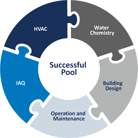
There is no “one thing” that will ensure a successful pool. Many things need to come together during the design and then during operations.
This puzzle helps illustrate the key factors needed for success. It is a coordinated effort. A proper design sets the stage for continued success for operation and maintenance.
The building itself also needs to be designed suitable for a higher temperature and dew point application. An indoor pool environment is different from traditional conditioned spaces and needs to be designed appropriately.
The building, HVAC system, and all equipment must perform reliably, day in and day out, ideally with minimum energy consumption, no matter the ambient temperatures or level of pool activity.
This guide is the culmination of decades of experience from a multitude of contributors and partners. We have seen first-hand what works and what doesn’t. This guide offers best practice advice based on what we have seen work successfully. While there are many details that need to be addressed, a great indoor pool environment should be something everyone expects, without compromise. While bad IAQ ultimately stems from water chemistry issues, there are things that need to be done on the HVAC side to provide the best possible comfort and air quality. That’s why we created this Natatorium Design Guide.
THE BASICS
The natatorium experience for a patron should be no different than in any other room in a building. It should be comfortable, healthy, and have good air quality. When designing a natatorium, the first recommended step for the designers is to meet with the facility owners to discuss the desired operating conditions and expectations. Only once the operating conditions and expectations are defined can the designer effectively calculate loads and address all the key design aspects.
A natatorium is one of the most notoriously difficult facilities to design because there are so many critical considerations that, if overlooked, can develop into serious problems affecting the building structure or result in an unpleasant experience or ill-health effects for the occupants. There are vital design aspects that must be considered in order to deliver a successful facility. These include relative humidity levels, condensation, air temperature, pool water temperature, pool activity levels, air distribution, outdoor air, exhaust air, pool water treatment, and chloramine control. This guide will cover all the key considerations for a successful facility. However, the two most critical design aspects that will be covered are chloramine control and air distribution.
There are new technologies available that will reduce and possibly eliminate chloramines. To ensure good air quality within a facility, an investment in one of these technologies is a must. UV water treatment and the Evacuator source capture system are two highly effective technologies for chloramine control. The treated and conditioned air must be delivered down into the breathing zone where the patrons are located if there is to be any reasonable expectation of providing good air quality and a comfortable experience.
Chapter TWO
Poor indoor air quality makes swimmers and lifeguards sick, plain and simple. Sadly, this is well documented and the bane of competitive swimming and the indoor pool industry in general. Temperature and relative humidity play a critical role in human comfort levels. It is essential that both are controlled and stable. While temperature control is generally well understood and mastered by designers, it is important to recognize the special temperature levels that natatorium patrons expect. The space temperatures in a natatorium are unique to each project and assumptions must never be made. Proper control of relative humidity levels is also a concern because of the direct effect on human comfort and health. Figure 1 demonstrates that relative humidity levels outside the optimum zone 40-60% range can result in human vulnerability to disease. These diseases include bacteria, viruses, fungi, mites, and other contaminants that lower air quality and will potentially lead to respiratory issues.
While 40% is certainly an acceptable indoor relative humidity level, most indoor pools do not operate at lower than 50% RH due to significantly increased operating costs.
- At lower RH levels, the pool evaporation rate increases dramatically. This increases both the dehumidification load and the pool water heating requirement.
- In cold climate applications, it is important to ensure no more outdoor air be introduced than what the codes require. More is not better in this case as it causes the RH levels to plummet to as low as 20%, dramatically increasing air and pool water heating costs.
- Swimmers leaving the water will also feel chilly at lower relative humidity levels due to evaporation off their bodies.
FIGURE 1: RELATIVE HUMIDITY IMPACTS OCCUPANT HEALTH

The type of facility being designed will typically dictate the space temperature. Table 1 helps target some typical conditions. It is critical to understand who will be using the facility in order to deliver the conditions most likely to satisfy them.
TABLE 1 – NATATORIUM DESIGN CONSIDERATIONS
| Pool Type | Air Temperature (°F) | Water Temperature (°F) |
|---|---|---|
| Competition | 75 to 85 | 76 to 82 |
| Diving | 80 to 85 | 84 to 88 |
| Elderly Swimmers | 84 to 85 | 85 to 90 |
| Hotel | 82 to 85 | 82 to 86 |
| Physical Therapy | 80 to 85 | 90 to 95 |
| Recreational | 82 to 85 | 80 to 84 |
| Whirlpool/Spa | 80 to 85 | 102 to 104 |
| Kids Swim Schools | 86 to 92 | 88 to 92 |
GENERAL NOTES
Discuss the planned operation of the facility with the operator to establish operating temperatures and general expectations.
- Facilities with warmer water temperatures tend to have warmer space temperatures. Warmer spaces have higher dew points and will have condensation issues unless the building is designed suitable for this application.
- Physical therapy facilities will often cater to the comfort of the therapist rather than the patient. The patient is generally not in the space for more than an hour, whereas the therapist is there all day. The designer should consult local codes. Some states require a full purge of the clinic room air with 100% outdoor air for every hour of occupancy.
- Elderly swimmers and kids swim schools tend to prefer much warmer air and water temperatures.
- Maintain relative humidity between 50% and 60% RH. Allowing the RH to go to 60% in summer will help reduce operating costs and equipment size while eliminating condensation concerns (condensation occurs only in cool/cold weather).
Chapter THREE
While warm space temperatures and 50-60% relative humidity levels are ideal for patron comfort, they also translate to high dew point conditions which can lead to condensation problems and serious damage to the building structure (in cool/cold weather). If the building structure itself has not been properly designed for this higher indoor dew point application, catastrophic results may occur. The architect should design and protect the building envelope based on an indoor dew point design condition.
Controlling humidity to provide this stable dew point condition year round requires that a total moisture load be accurately calculated. This moisture load must be removed from the space at the same rate it is generated in order to maintain stable space conditions.
It is imperative that the designer know what the operating temperatures will be in order to properly establish loads.
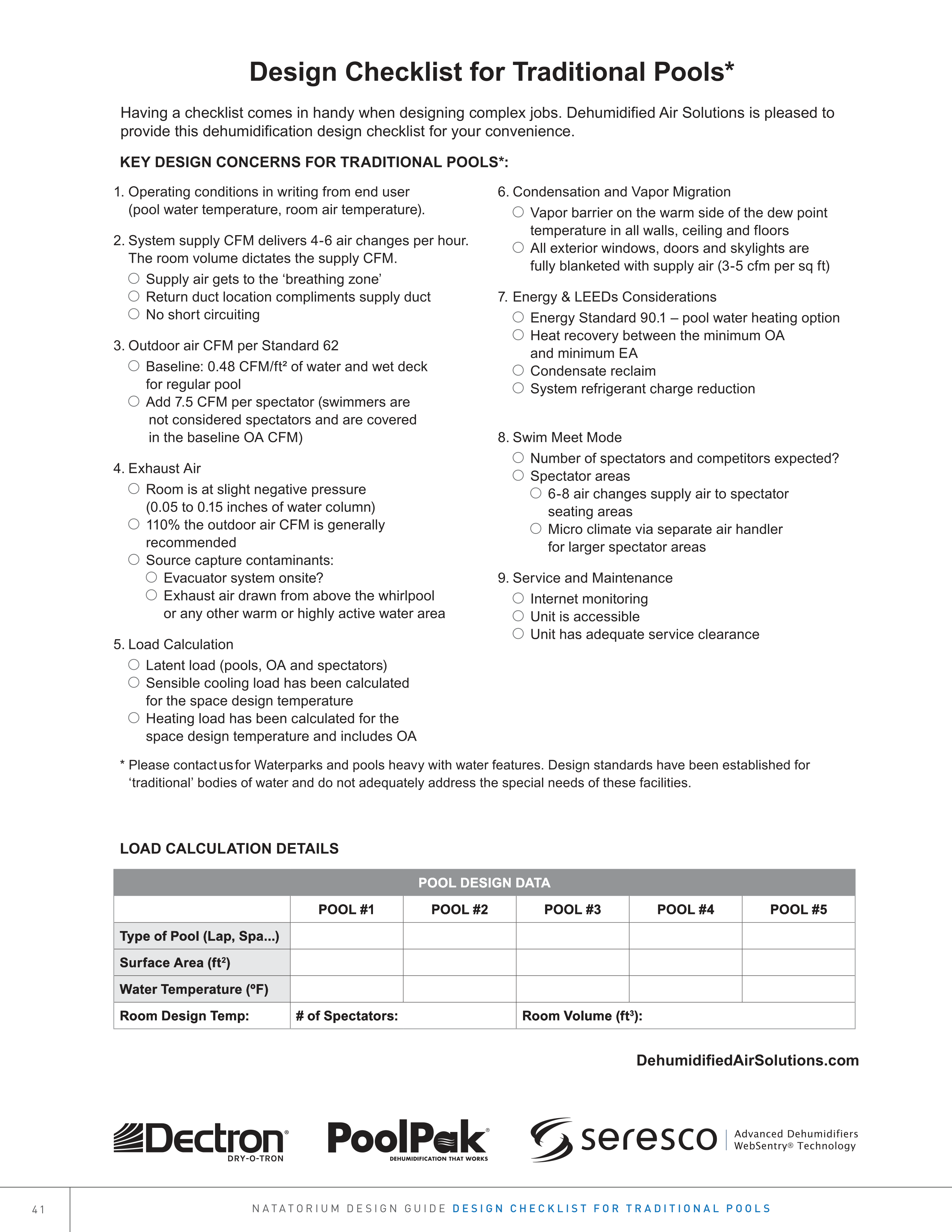
SEASONAL LOAD CALCULATION
Every building’s moisture (latent) load is calculated the same way. There are generally three sources of moisture that are considered:
- Internal load (pool evaporation)
- Occupants
- Outdoor air load
In the summer, the outdoor air tends to be a load, but since it is warm outside, condensation is not a concern, so it is recommended to model the space at 60% RH.
In the winter, there is significant risk of condensation, so it is recommended to model at 50% RH. The outdoor air in winter almost always is a dehumidification credit, making this easily achievable.
POOL EVAPORATION
The internal load in a natatorium is the evaporation from the pool water and continuously wet surfaces. In a natatorium, this represents the majority of the total dehumidification load. Consequently, it is essential to accurately predict the pool evaporation.
There are five variables used to calculate the evaporation rate:
- Pool water surface area
- Pool water temperature
- Room air temperature
- Room air relative humidity
- Pool water agitation and activity factor
The first four variables are straightforward and should be dictated by the owner. They are used to calculate the baseline (unoccupied) evaporation rate in the natatorium.
The activity factor is the fifth variable. It is used to evaluate how much water agitation and splashing is expected when the pool is in use and how that increases the evaporation from the baseline value. Chapter 6 of ASHRAE’s HVAC Applications Handbook publishes an activity factor table (Table 2) based on years of empirical field and test data.
TABLE 2 – ACTIVITY FACTORS
| TYPE OF POOL | ACTIVITY FACTOR |
|---|---|
| Elderly Swim | 0.65 |
| Fitness Club — Aquafit | 0.65 |
| Hotel | 0.8 |
| Institutional — School | 0.8 – 1.0 |
| Physical Therapy | 0.65 |
| Public/YMCA | 1.0 |
| Residential | 0.5 |
| Swim Meet | 1.0 |
| Wave Pool | 1.5 – 2.0 |
| Whirlpool | 1.0 |
(FLATWATER) EVAPORATION RATE EQUATION
Equation #2 in chapter 6 of ASHRAE’s 2019 HVAC Applications Handbook calculates the evaporation rate in pounds of water per hour (lb/h) for air velocity over water at 10-30 fpm. The vapor pressure values can be found in steam tables.
ER = 0.1 x A x AF (Pw – Pdp)
where
ER = evaporation rate of water, lb/h
A = area of pool water surface, ft2
AF = activity factor (Table 2)
Pw = saturation vapor pressure at water surface, in. Hg
Pdp = partial vapor pressure at room dew point, in. Hg
As evident by the equation, the following factors increase the evaporation rate:
- Increasing water temperature
- Lowering air temperature
- Lowering air relative humidity
- High activity/agitation
Once equipment has been selected and installed, any change of the variables that increases the evaporation rate can result in equipment no longer being suitable for the new larger load.
WATER FEATURES AND TOYS
It is important to understand that the entire effective water surface area and relative velocity (air and/or water) is required to estimate evaporation.
Manufacturers of water features and toys do not publish the evaporation loads from their products, forcing engineers to estimate. As a result, any indoor space heavily laden with water toys will make it difficult to accurately model dehumidification loads, so it is important for designers to set expectations with the owner. For example, there should not be an expectation that exact relative humidity levels will be maintained.
OCCUPANT LOAD
Swimmers are not usually considered occupants as they are submerged in the water. Swimmers and their water agitation are included in the activity factor. Spectators, especially in facilities that host large swim meets, can total several thousand – and add a significant moisture load (Table 3).
TABLE 3 – OCCUPANTS’ LATENT LOAD
| ACTIVITY LEVEL | LB/H PER SPECTATOR |
|---|---|
| Quietly Seated | 0.155 |
| Moderate Activity | 0.205 |
| Enthusiastic | 0.250 |
| Highly Enthusiastic | 0.530 |
SWIM MEETS
Facilities that host swim meets have two distinct modes of operation: normal daily use and swim meets.
To evaluate the peak dehumidification load during swim meets (which occurs during the warm-ups), an activity factor of 1.0 should be used. The total number of spectators and competitors on the pool deck must also be included in the load. Codes also generally require that each spectator be provided with 7.5 CFM of outdoor air. The load impact of the outdoor air must also be calculated.
Facilities should size equipment based on the larger of the two main operating modes.
SPECTATOR GALLERIES
If there is a dedicated spectator gallery of a suitable size, there could be an opportunity to create a separate microclimate for them during swim meets using a dedicated spectator HVAC unit. A dedicated HVAC unit can deliver the extra outdoor air needed to this area during the meet while also providing a slightly different (usually cooler) space condition that is more comfortable for the spectators.
OUTDOOR AIR
The introduction of outdoor air is essential to maintaining good air quality in any facility. The impact of this outdoor air ventilation on a natatorium changes with the weather and the geographic location of the facility. Introducing outdoor air during the summer generally adds moisture to the space, and in the winter, removes moisture from the space. For maximum dehumidification load calculations, the summer design conditions are considered.
Construction codes generally require that outdoor air be introduced into a commercial building during occupied hours. ASHRAE Standard 62 Table 6.1 recommends the introduction of outdoor air into a natatorium at the following rates:
- 0.48 CFM/ft2 of pool water and wet deck area
- Some versions of Table 6.1 call for 0.06 CFM/ft2 dry deck as base line
- 7.5 CFM per spectator added to the base line during swim meets
The purpose of this outdoor air, in part, is to help dilute chemicals off-gassed from water. Exceeding code requirements for outdoor air will not necessarily provide better air quality. In winter, it will significantly increase the operating expenses, and in summer, may increase the dehumidification load.
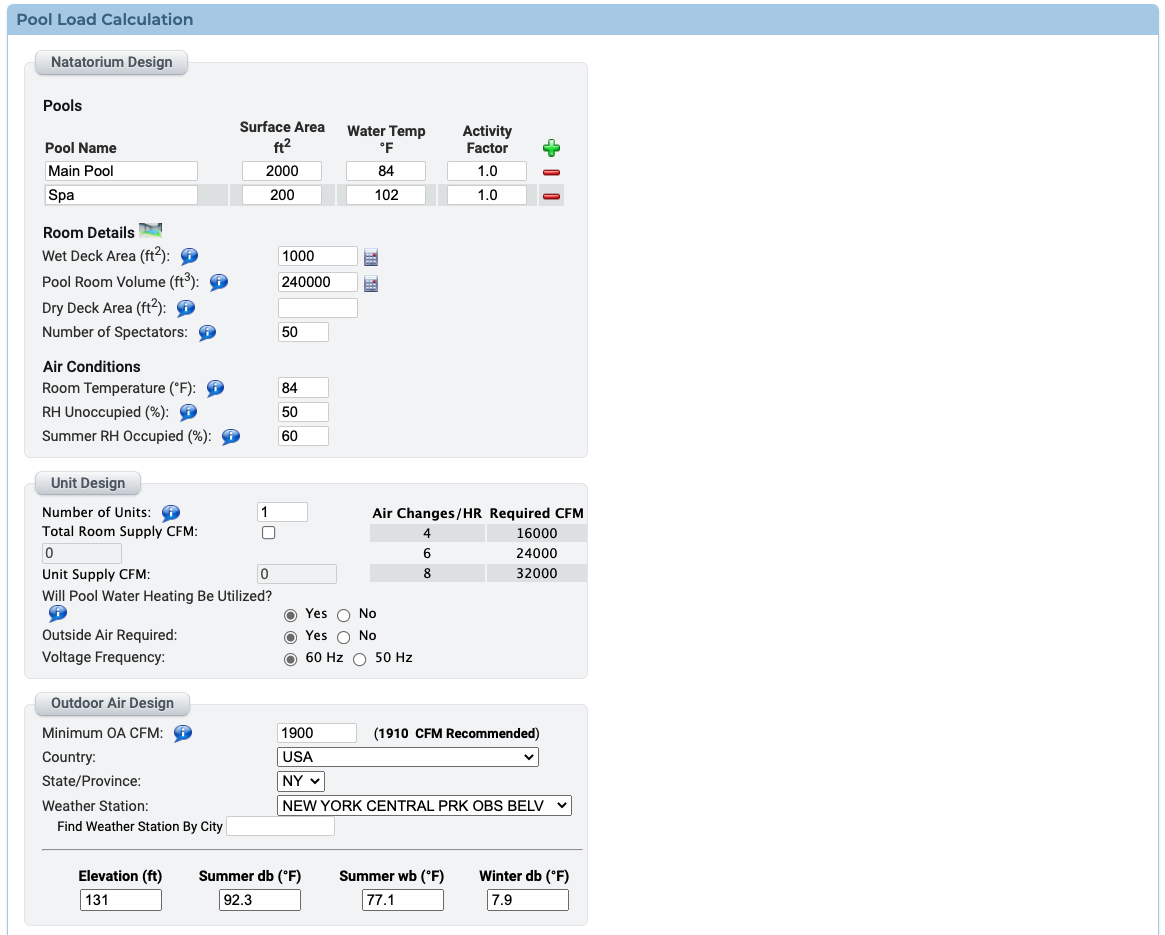
LOAD ESTIMATION SOFTWARE
There is software based on ASHRAE criteria that calculates all moisture loads in a matter of minutes. Figure 2 provides a snapshot of the basic data that would generally need to be entered to calculate a load.
FIGURE 2: POOL LOAD CALCULATION
Chapter FOUR
Good indoor air quality must be a primary goal for all. If it is a top concern, it will get the attention it needs and deserves.
The definition of acceptable indoor air quality for an indoor pool is something the Council for the Model Aquatic Health Code’s (CMAHC) research is trying to define for North America. Currently, there is no definition regarding what chemical levels are acceptable before having a negative impact on human physiology.
The World Health Organization (WHO) has established a guideline of 0.5 mg/m3 for gas-phase NCl3 (trichloramine) concentration in pools. A slightly more stringent value of 0.3 mg/m3 was suggested by a research group from Belgium. A possible outcome of the project described herein is identification of a different guideline for gas-phase NCl3 concentration, but for now, most recognize the need to stay under 0.5 mg/m3.
Part of CMAHC’s research is to find a means to measure trichloramine levels with commercially available sensors in HVAC systems. Currently, there are no viable trichloramine sensors that can be used in HVAC, so the research is hoping to find a suitable replacement, perhaps similar to VOC or CO2 levels. Once that is established, HVAC system control strategies will be able to adjust based on the chemical levels in the space. While this can have an impact on the IAQ, it will always be reactive to the chemicals already being off-gassed. Addressing water chemical levels directly will have a more immediate impact on IAQ because fewer chemicals will off-gas. Maintaining optimal chemical levels should always be the focus when trying to achieve the best possible IAQ.
Designers that follow ASHRAE Handbook guidelines, as well as those recommended in this guide, should have every expectation of a great space condition and a pleasant indoor pool experience. There are steps a design engineer must take to minimize the chances that a patron experiences discomfort or ill health effects. There are many factors that impact the IAQ in a natatorium. These include pool water chemistry problems, inadequate outdoor air, air stagnation, poor air distribution, high humidity, facility maintenance and operation, as well as occupant/swimmer behavior (urine in pools is responsible for 50% of chemical issues).
Four key factors having the most direct impact on indoor air quality are under the control of the design engineer:
- Poor air distribution – no airflow in the breathing zone
- Air change rate
- Outdoor air ventilation
- Exhaust air – chemical source capture
Factors that have a significant impact on IAQ but are not under the control of the HVAC design engineer are pool water chemistry, maintenance, operation, and patron behavior. It is vital that these are addressed by the facility operator.
BREATHING ZONE
The single most important focus of the HVAC design is to provide adequate supply air down into the breathing zone. The supply air from the HVAC system has been conditioned and filtered with outdoor air blended in. It is the best quality air the system has to offer. When supply air is delivered down into the breathing zone, patrons will enjoy the best possible air quality.
A properly designed facility will adequately control and remove chloramines while providing the treated and conditioned air to where it is most needed – into the breathing zone and deck area.
AIR CHANGE RATE
ASHRAE recommendations for proper volumetric supply air changes per hour are important to ensuring that the entire room will see air movement. Stagnant areas must be avoided, as they will be prone to condensation and air quality problems.
Short circuiting between supply and return air must also be avoided as it significantly reduces the actual air changes within the space and the overall effectiveness of the HVAC system.
ASHRAE recommends:
- 4-6 volumetric air changes per hour in a regular natatorium
- 6-8 volumetric air changes per hour in spectator areas
A quick calculation will determine the supply air requirement:
- Supply air required (CFM) = room volume (ft3) x desired air changes / 60
The room volume determines the amount of supply air a space requires.
OUTDOOR VENTILATION AIR
The amount of outdoor air to be introduced to the facility is determined by local codes. Most codes adopt ASHRAE Standard 62. Outdoor air is critical towards diluting airborne chemicals and maintaining good indoor air quality.
Facilities that introduce outdoor air per ASHRAE Standard 62 and have proper/effective air distribution will have outstanding IAQ.
- More outdoor air than required by ASHRAE Standard 62 is not required for good IAQ if the air distribution is done well (except for indoor water and splash parks).
- Outdoor air requires a significant amount of heating energy in the winter and must be included in heat load calculations.
- Heat recovery should be considered between the exhaust air and outdoor air streams.
- Introduce the outdoor air at the factory-provided intakes on the air handlers.
- Locate outdoor air intakes away from sources of airborne contamination, such as exhaust fans or plumbing vents.
- The outdoor air may need to be preheated to 65°F if more than 35% of the total airflow is outdoor air or if the winter design temperature is below 10°F.
- A certified air-balancing contractor must balance the system airflow.
All air handlers for indoor pools must be equipped with an outdoor air connection, filter, two-position motorized damper, and balancing damper.
EXHAUST AIR
ASHRAE recommends the room be maintained at 0.05-0.15” WC negative pressure relative to surrounding spaces.
10% more exhaust air than outdoor air is a good rule of thumb.
More exhaust air than recommended by ASHRAE will not reduce or stop moisture migration through the building envelope to the outdoors in cold weather. Vapor migrates based on vapor pressure differential. There is effectively a 10” WC pressure differential between indoors and outdoors on cold winter days. There is no amount of negative airside pressure that can be added to a space to stop vapor migration. To prevent this, vapor retarders must be placed in appropriate locations throughout the entire building envelope.
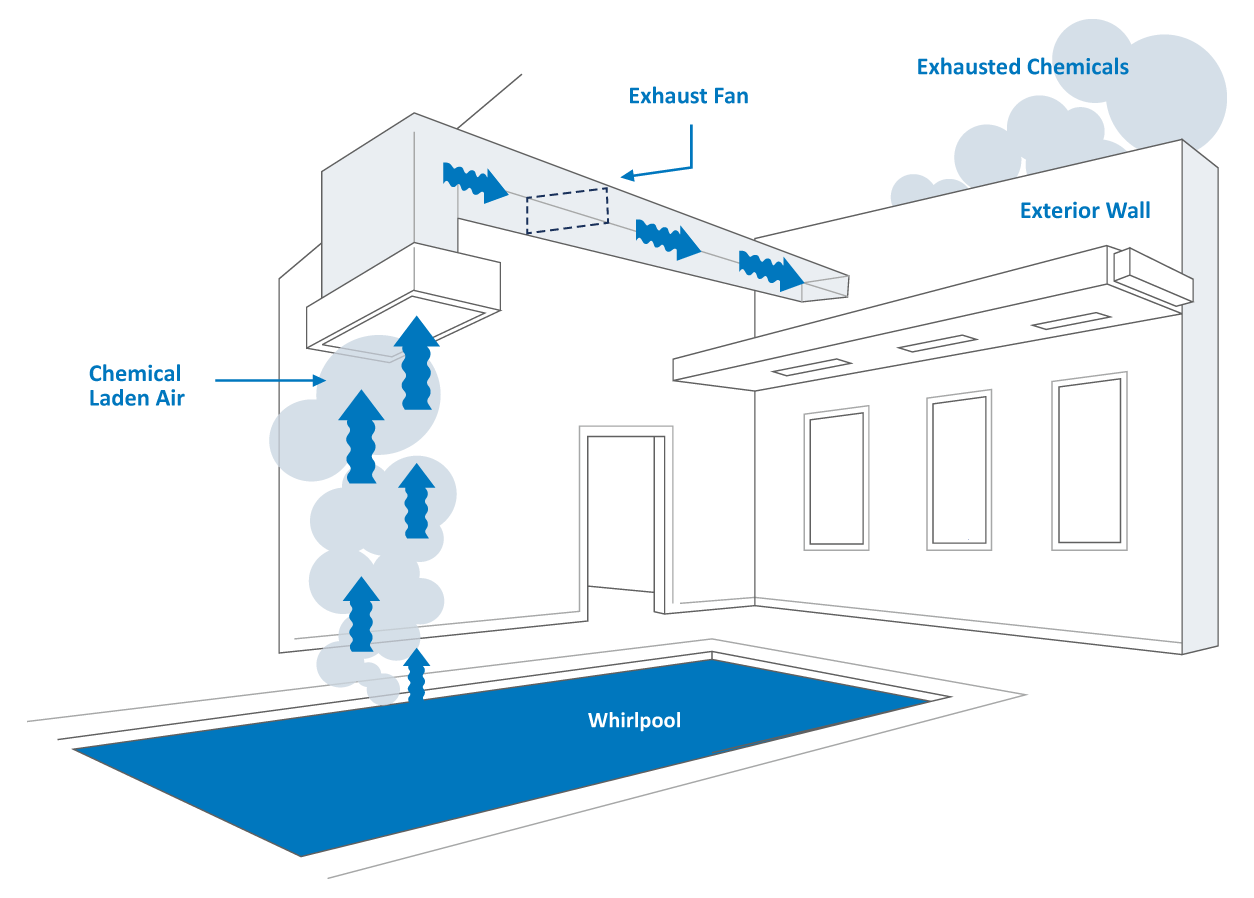
Figure 3 illustrates how the strategic location of the exhaust grille can also significantly improve the air quality in the space. An indoor spa or whirlpool should have the exhaust air intake grille located directly above it. This source captures and extracts the highest concentration of pollutants before they can diffuse into the space and negatively impact the room air quality.
10% more exhaust air then outdoor air is a good rule of thumb.
FIGURE 3: EXHAUST AIRFIGURE
CHEMICAL SOURCE CAPTURE EXHAUST BENEFIT
If the Evacuator is being used, it addresses the exhaust air requirements of the space while providing a terrific secondary HVAC benefit. Since it exhausts directly from the water surface, that air gets replaced by air from the space. This enhances the breathing zone by helping draw air down all the way to the water and deck surface.
POOL WATER CHEMISTRY
If there are no chemicals off-gassing, there is no air quality issue. All efforts towards minimized chemical off-gassing in the design and operation of the pool will directly impact the IAQ. Pool water chemistry and facility operation are key variables impacting IAQ that are not generally under the control of the design engineer.
Good pool water chemistry is critical in order to achieve high levels of human health and comfort. Maintaining ideal pool water conditions also ensures the best possible indoor air quality and optimal performance from the mechanical system.
There are new technologies available to help with water chemistry and chloramine management, such as the Evacuator system and ultraviolet (UV) light treatment systems.
CHLORINE SMELL
It is a common misconception that a strong chlorine odor is caused by too much chlorine in the water. The odor is actually caused by chloramines (combined chlorines) off-gassing from the pool water surface.
Chloramines are formed in the pool water when there is insufficient free chlorine in the pool to address the nitrogen-containing compounds brought into the pool water by the swimmers. These nitrogen compounds are naturally occurring and contained in sweat, urine, body oils, and other proteins that get released into the pool water. If the introduction of these nitrogen compounds outpaces the introduction of free chlorine, the chlorine combines with the nitrogen compounds rather than fully oxidizing them.
The chloramine levels increase in the water, resulting in an increase in chloramine off-gassing, which creates the odor of chlorine in the room. There are three different types of chloramines that can form: monochloramine, dichloramine, and trichloramine. Trichloramine is the most volatile and will off-gas most quickly.
Off-gassed chloramines have a strong attraction to the airborne humidity and will combine with moisture in the air. Consequently, any condensation of the space humidity will become corrosive.
SOURCE CAPTURE CHEMICAL EXHAUST
A very effective method of chloramine control is to source capture them off the water surface and exhaust them before they have a chance to become an IAQ problem. The Evacuator system was designed for exactly this purpose. The result is top notch air quality, even on retrofitted systems.
Ultraviolet light treatment of pool water has shown to have a very positive impact on the water chemistry and can help significantly reduce chloramines (if not eliminate them entirely). This approach to water treatment is gaining popularity, and as positive data continues to be released, should become the norm.
HUMIDITY AND CORROSION
Any condensation of the space humidity will become corrosive. It is critical that the space humidity levels be controlled to prevent condensation, as it will damage the building and mechanical system.
By design, indoor pool environments are warmer and, as a result, have higher dew point temperatures compared to traditional spaces.
Engineers and architects must understand the consequences of moist corrosive air and pay special attention to its potential impact on the entire HVAC system and building envelope.
It is a best practice to ensure that all electrical components are located in a separate mechanical vestibule, protected from the pool air stream. All components in contact with the pool air stream should be protected with the best possible corrosion resistant paints, coatings, and materials available.
Chapter FIVE
While 50-60% relative humidity levels are ideal for patron comfort and health, they are much higher than in traditional spaces in winter. In cold climates, it is very common to humidify in order to get the humidity levels up to 30-40%. An indoor pool and humidified space can experience condensation problems and serious damage to the building structure in cold weather if they are not designed properly.
Condensation is a major concern for all types of building construction. Condensation triggers a destruction process, as it leads to the growth of mold and mildew. If allowed to occur inside the building walls or roof, condensation will cause deterioration and can devastate the structure by freezing in winter.
It is critical that condensation be avoided at all costs.
The building design and construction must be appropriate to house an indoor pool and must be suitable for 50-60% relative humidity year round.
A successful design will identify and blanket building elements that have low R-values (typically exterior windows) with warm supply air to prevent condensation. Window frames and emergency exit doors must also be thermally broken to avoid condensation.
DEW POINT TEMPERATURE
Condensation forms on surfaces when surface temperatures are lower than the dew point of the surrounding air.
The first step in condensation control is to establish the space dew point temperature based on the desired space conditions. With that information, the designer can establish potential condensation spots in the building. A pool’s indoor design dew point will typically range from 62-69°F (82-84°F 50-60% RH). Contrast this to a typical space in winter that might be 70°F 40% RH, which has a 45°F dew point.
Pools have a much higher likelihood of condensation because of both an elevated space temperature and slightly higher relative humidity, resulting in a very high dew point.
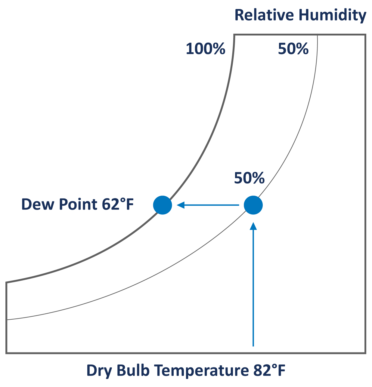
These are building elements with low R-values that will have an inside surface temperature below the dew point at winter design condition. Most importantly, the dew point also establishes where to locate the vapor retarder in the wall. Figure 4 shows that a typical pool design of 82°F 50% RH has a dew point of 62°F.
Therefore, any surface with a temperature below 62°F will condense moisture.
FIGURE 4: DEW POINT TEMPERATURE
VAPOR RETARDER
A vapor retarder is a material that restricts the rate of water vapor diffusion through the ceilings and walls of a building when below dew point temperature occurs. Figure 5 illustrates how failure to install the vapor retarder in the proper location will result in condensation within the structure. Condensation in the walls or roof can lead to structural failure. A vapor retarder should be sealed at all seams.
FIGURE 5: DO NOT BUILD AN INDOOR POOL WITHOUT A VAPOR RETARDER
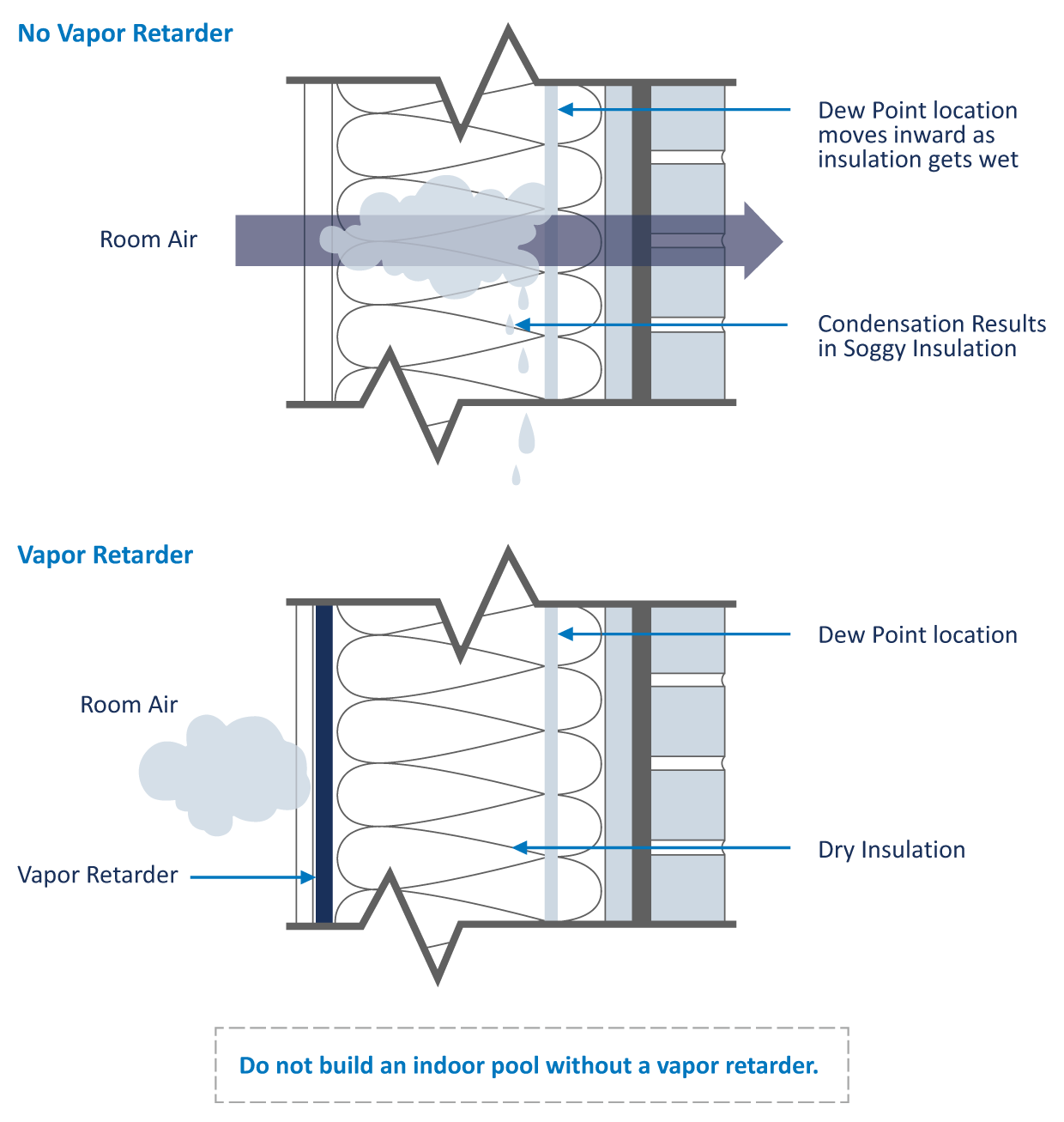
It is important to ensure the entire pool enclosure design (walls and ceilings) has a vapor retarder in the correct location. Care must be taken where walls and roof and walls and floor meet to ensure there is no breach in the vapor barrier.
A properly located and installed vapor retarder is the only means of protecting a building structure from vapor migration that results in moisture damage.
Figure 6 is an example of a wall detail with its temperature gradient. This exercise allows the designer to identify the dew point temperature in the wall and where the vapor retarder must be installed.
FIGURE 6: POOLS ARE DIFFERENT – INSTALL THE VAPOR RETARDER ON THE WARM SIDE OF THE DEW POINT

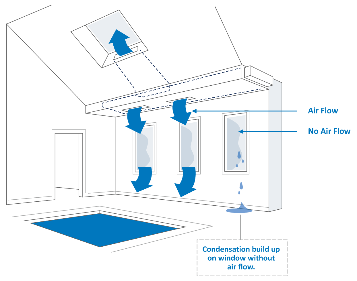
WINDOW DESIGN
Windows have a relatively low R-value and, as a result, will have surface temperatures below the pool room dew point when outside temperatures are cool. Exterior windows will develop condensation on the first cold day unless preventative measures are taken. The solution to the condensation problem is to fully blanket every part of the window with supply air from the HVAC system. It is critical that no section be missed, or the window will get cold and condense.
FIGURE 7: WINDOW DESIGN
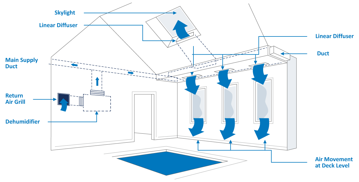
AIR DISTRIBUTION
Since exterior windows and exterior doors are a primary condensation concern, it is extremely important that the supply air is focused in these areas. The warm air from the dehumidifier will keep the window surface temperature above the dew point temperature and in turn, ensure the windows and exterior doors remain condensation free.
There are five basic steps to laying out the ductwork for the best air distribution:
- Supply air to the breathing zone at the deck level and water surface.
- Supply air to exterior windows and doors.
- Supply air to the remainder of the room to ensure there are no stagnant areas.
- Locate the return duct where it will optimize the entire airflow pattern.
- Prevent air short-circuiting by avoiding supply air diffusers near the return grille.
Figure 8 illustrates good air distribution practices.
FIGURE 8: PERIMETER DUCT LAYOUT
All air distribution systems should:
- Satisfy ASHRAE design requirements and local codes.
- Supply at least 4-6 volumetric air changes per hour.
- Blanket exterior windows, exterior surfaces, and other areas prone to condensation with supply air. A good rule of thumb is 3-5 CFM per ft2 of exterior glass.
- Locate the return grille to enhance the overall air pattern within the room.
- Select grilles, registers, and diffusers that deliver the required throw distance and the specified CFM rating.
- Introduce outdoor air per local codes and/or ASHRAE Standard 62.
- Maintain a negative pressure in the space with an exhaust fan.
- Have an air balance performed.
GENERAL RECOMMENDATIONS:
- Galvanized sheet metal ducts are acceptable in most installations.
- A below-grade duct system should use PVC or plastic-coated galvanized spiral pipe to avoid deterioration.
- Stainless steel duct and hardware should be avoided as they are readily attacked by chlorine.
- Fabric duct is an excellent choice of duct material for a natatorium.
- The duct material should not allow air to leak.
- The location of supply grilles and overall duct layout should be exactly the same as with a metal duct.
- Ductwork that passes through an unconditioned area should be insulated on the exterior.
- When applicable, locate exhaust fan air intakes as close to the whirlpool as possible.
- To prevent excessive vibration noise, install neoprene flex connectors when attaching ductwork to the dehumidifier. Acoustic insulation on the duct close to the unit may also be a consideration.
- Skylights require significant airflow to avoid condensation on their surfaces.
Chapter SIX
Reducing energy consumption is an earth-friendly and green focus that also reduces operating costs and monthly bills.
Choice of operating conditions and building envelope should be discussed during the design phase in order to ensure optimal energy consumption and performance. For example, an all-glass structure is going to be expensive to heat and difficult to keep condensation-free in a cold climate.
A natatorium has five major areas of energy consumption:
- Pool water heating
- Dehumidification
- Space heating in winter
- Space cooling in summer
- Outdoor air heating and cooling
OPERATING CONDITIONS
Pool water heating and evaporation rates are always interrelated. Every pound of moisture evaporated to the space is a load to be dehumidified, and it also represents heat lost by the pool water. Approximately 90% of an indoor pool’s annual water heating cost is due to evaporation losses. Every pound of moisture evaporated represents ~1000 Btu of heat lost from the pool water body, and unless a pool is covered, that heat is lost 24/7.
- The warmer the pool water, the higher the evaporation rate.
- The lower the space relative humidity level, the higher the evaporation rate.
- The lower the room temperature (dew point), the higher the evaporation rate.
At the same water temperature, a pool in a room at 78°F 50% RH will evaporate almost 35% more than that same pool in an 85°F 50% RH room. While the space temperature should be dictated by the owner based on what satisfies their patrons, it is useful to be aware of a few guidelines that can help with energy consumption:
- Maintaining the room air temperature as warm as possible (usually 2-4°F above the pool water temperature) will help reduce evaporation. Most applications don’t want to see air temperatures above 86°F per ASHRAE guidelines; however, indoor pools sometimes go beyond that recommendation, with kids swim schools seeing air as warm as 92°F and some elderly swim programs exceeding that recommendation as well. Reducing the evaporation in turn reduces the pool water heating requirement as well as the dehumidifier size.
- Introducing more outdoor ventilation air than required by code will impact the space RH levels in summer and winter. In winter, the space relative humidity levels will drop below 50%, which increases the evaporation rate and pool water heating requirement.
SEASONAL RH LEVELS
In the summer, the outdoor air tends to be a load, but since it is warm outside, condensation is not a concern. In this case, it is recommended to model the space at 60% RH.
In winter, there is significant risk of condensation, so it is recommended to model the space at 50% RH. The outdoor air in winter almost always is a dehumidification credit, making this easily achievable.
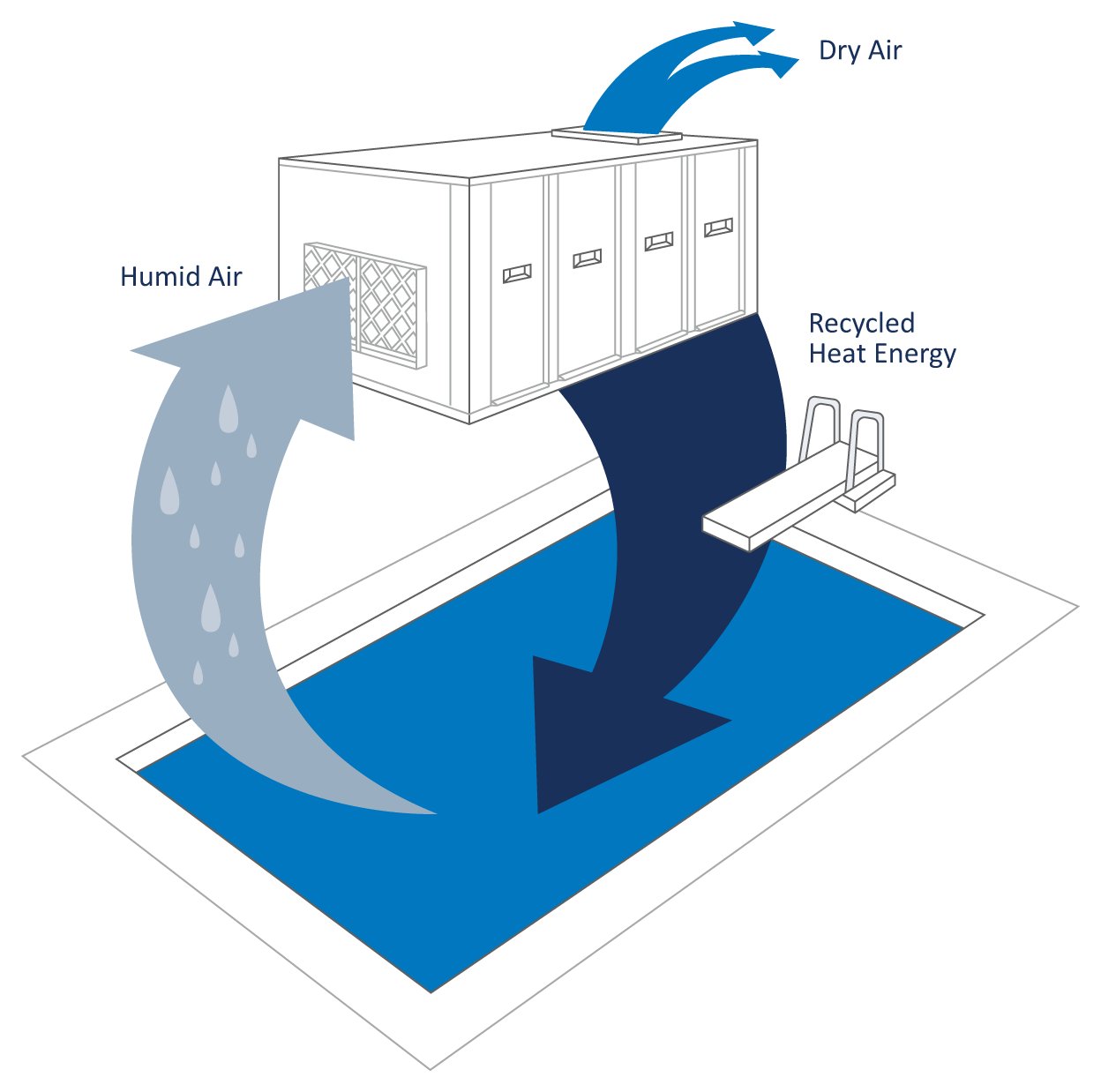
POOL WATER HEATING ENERGY RECOVERY
When using a refrigeration-based approach to control humidity, the dehumidification process captures energy in the refrigerant at the evaporator coil. The latent heat component is essentially the pool’s evaporation. Evaporation represents a significant portion of the pool’s annual water heating requirements. This captured energy can be returned to the pool water to provide free heating (Figure 9).
A dehumidifier with a pool water heating option has an enormous potential for energy savings. This process has an impressive coefficient of performance of 8.
The use of the pool water heating option satisfies ASHRAE Energy Standard 90.1; otherwise, a pool cover is required to meet the standard.
A refrigeration-based dehumidifier can use up to 100% of the compressor hot gas waste heat to heat the pool water and/or reheat the air. Returning this free energy back to the pool water or room air greatly reduces the annual heating costs. During winter, the dehumidifier is capable of providing 100% of the pool’s water-heating requirement.
The mechanical refrigeration system approach to controlling the environment in a pool is a unique use of the refrigeration system. The evaporator controls the humidity, while the compressor hot gas can be used to heat the pool water and/or room air simultaneously. Traditional air conditioning systems merely send the compressor hot gas outdoors to a condenser or cooling tower and do not tap into this heat source.
Due to increased energy savings, the pool water heating option typically pays for itself in less than one year.
Table 4 highlights the annual contribution towards water heating from the dehumidifier while operating in cooling mode. A pool with a 50 lb/hr evaporation rate and a cooling season of 2,000 hours would realize an annual savings of $2,350 if the primary source of pool water heating was an electric heater.
Calculations are based on the following: 1000 Btu/lb latent heat of vaporization. Gas: $0.60 per 100,000 Btu, efficiency = 75%. Electricity: 8 per kWh.
Most pools require an auxiliary pool water heater. When the dehumidifier is not able to provide full water heating, it can control the auxiliary heater.
TABLE 4 – ANNUAL WATER HEATING SAVINGS FROM POOL HEATING OPTION
| ANNUAL SAVINGS FROM POOL WATER HEATING OPTIONS | |||||||||
|---|---|---|---|---|---|---|---|---|---|
| Cooling Season | Heat Source | Average pool evaporation (lb/h) | |||||||
| 20 | 30 | 40 | 50 | 100 | 150 | 200 | 300 | ||
| 4000 hours | Gas | $640 | $960 | $1280 | $1600 | $3200 | $4800 | $6400 | $9600 |
| Electricity | $1880 | $2820 | $3760 | $4700 | $9400 | $14100 | $18800 | $28200 | |
| 2000 hours | Gas | $320 | $480 | $640 | $800 | $1600 | $2400 | $3200 | $4800 |
| Electricity | $940 | $1410 | $1880 | $2350 | $4700 | $7050 | $9400 | $14100 | |
A dehumidifier with a pool water heating option has an enormous potential for energy savings.
FIGURE 9: THE ENERGY CYCLE
The ROI on a pool water heating option is less than 1 Year.
SPACE HEATING
As with every other room being designed, the cooling and heating load calculations should be performed for the natatorium. That is the only way to ensure the specific heating and cooling requirements are met. The room air temperature of an indoor pool facility is generally 10-15°F warmer than a typical occupied space, so the heating requirement per square foot of a natatorium will be considerably higher than a traditional room. Outdoor air must be included in load calculations as it often represents up to 50% of the heating load.
SPACE COOLING
Most patrons prefer buildings with year-round temperature control. Even though the space is generally 10-15°F warmer than a typical room, most patrons would find it objectionable to be in a space that has no cooling at all.
Space cooling is a free byproduct from packaged dehumidifiers and chilled water systems. These systems can provide year-round temperature and humidity control. They dehumidify by cooling the air below its dew point and condensing moisture at the cooling coil. If the cooling load exceeds the standard output of a dehumidification unit, a larger unit with compressor staging is often specified.
Outdoor ventilation air is essential for maintaining good IAQ.
OUTDOOR AIR, EXHAUST AIR, AND ENERGY RECOVERY
Outdoor ventilation air is essential for maintaining good IAQ in the pool and is a code requirement. The natatorium needs to be maintained at a slight negative air pressure, so warm “energy rich” air needs to be exhausted.
Outdoor air must be cooled and dehumidified in the summer and heated in the winter. In cold climates, outdoor air has the biggest impact in winter where it reduces the space relative humidity levels and represents a significant portion of the natatorium’s heating requirement. Outdoor air in winter may need to be heated 100°F to become neutral to the space temperature. In southern regions, the outdoor air introduces a lot of moisture and increases the dehumidification load.
The designer has several energy issues to consider:
- Introducing more outdoor air than codes require is not recommended:
– In winter, it will increase space heating and pool water heating costs significantly.
– Too much outdoor air in winter can also lower the relative humidity levels to uncomfortable levels for the patrons.
– In summer, it can introduce so much additional moisture that larger equipment could be needed.
- Warm “energy rich” air is required to be exhausted from the space to maintain negative pressure and good IAQ.
Energy recovery from the “energy rich” exhaust air should be considered.
FIGURE 10: HEAT EXCHANGE

Air-to-air heat exchangers are available for both sensible heat recovery and total energy recovery. Sensible-only devices are used in natatoriums. All sensible recovery devices are effective, but some are better suited to provide a cost-effective solution. Figure 10 highlights two examples. There are several questions that must be answered to determine which heat recovery approach is best suited for a particular facility:
- Is the installation in a cold climate application?
- Does the outdoor ventilation air need to be conditioned in order to avoid condensation when blended with the room air in summer and winter?
- Are the outdoor ventilation air and exhaust air streams within close proximity to each other?
- What is the return on investment?
GLYCOL RUNAROUND LOOP
Heat recovery is generally packaged as part of a dehumidifier when outdoor or rooftop installations are specified. Figure 11 shows a schematic of a recommended glycol runaround loop heat recovery method. This heat recovery option can be packaged seamlessly within the dehumidifier or remotely installed in the ductwork. The plate heat recovery devices in Figure 10 require special and complicated air paths within the unit. This increases the unit size and cost and also has a large airside pressure drop, which increases blower motor sizes and operating costs.
The annualized energy recovery of the glycol runaround loop outperforms any other form of heat recovery.
FIGURE 11: PACKAGED HEAT RECOVERY
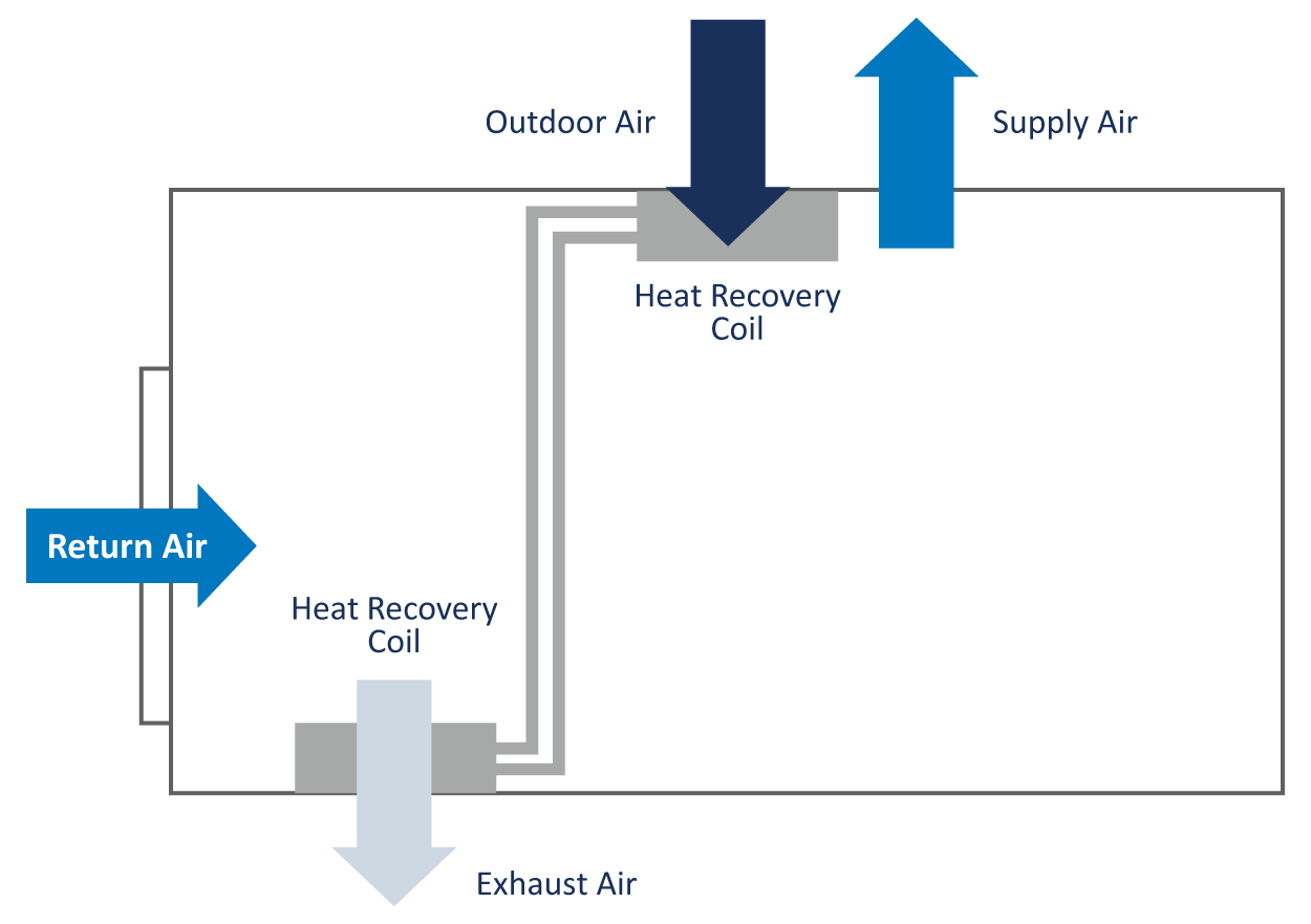
The glycol runaround loop approach to heat recovery offers the best performance and design flexibility in the smallest cabinet possible. This heat recovery coil set fits directly onto the outdoor air and exhaust air openings already provided on the unit without increasing the cabinet size. They are also easily sized to meet the specific requirements of the facility. The result is a compact, cost-effective heat recovery option that outperforms other technologies. The compact nature of this design results in lighter-weight cabinets compared to units integrating plate heat recovery technology. This is an important consideration on applications where roof loads are a concern.
The glycol runaround loop approach is well suited for the corrosive indoor pool environment as it offers superior corrosion protection compared to plate heat recovery devices.
The glycol runaround loop approach is also well suited for cold climate applications. On the coldest winter days, when heat recovery is needed the most, other heat recovery devices require the bypassing of air to prevent the device from freezing. However, the glycol approach does not present this risk.
The introduction of the heat recovery coils into the existing air streams offers a substantially lower overall airside pressure drop compared to units with dual air paths and complicated internal air patterns. This configuration offers the end user the lowest possible operating cost while providing the best possible heat recovery effectiveness.
A heat recovery option in a cold climate application will typically pay for itself after one year due to increased energy savings.
The savings are noteworthy even in a mild climate, where these devices generally pay for themselves in two to three years.
TABLE 5 – ENERGY RECOVERY CALCULATION
| WEATHER DATA | ||
|---|---|---|
| City | Average °F T1 | Winter °F T2 |
| Atlanta | 61 | 17 |
| Boston | 51 | 6 |
| Buffalo | 43 | 2 |
| Chicago | 51 | -8 |
| Dallas | 65 | 18 |
| Denver | 50 | -5 |
| Detroit | 49 | 3 |
| Minneapolis | 45 | -16 |
| Indianapolis | 52 | -2 |
| Nashville | 60 | 9 |
| New York | 54 | 11 |
| Oklahoma City | 60 | 9 |
| Pittsburgh | 50 | 3 |
| Portland, OR | 53 | 17 |
| Salt Lake City | 52 | 3 |
| Seattle | 51 | 20 |
| St-Louis | 55 | 2 |
| Toronto | 46 | -5 |
| HEAT RECOVERY SAVINGS (Q) ANALYSIS | |||
|---|---|---|---|
| Pool Location | Atlanta | ||
| T1 | Average Outdoor Temperature | 61 | °F |
| T2 | Winter Design Temperature | 17 | °F |
| T3 | Indoor Design Temperature | 85 | °F |
| V | Outdoor Air Volume | 3500 | CFM |
| N | Occupied Hours | 12 | Hours |
| ER | Electric Rate: | 0.06 | $/kW |
| GR | Gas Rate: | 0.65 | $/CCF |
| GE | Gas Heating system efficiency: | 60 | % |
| Space Heating by: | GAS | ||
| HE | Heat Recovery Efficiency | 50 | % |
| Q | {t3-T1} x 1.08 x V x {8760*N/24} x GE | 190400 | MBH |
| ANNUAL SAVINGS FROM HEAT RECOVERY DEVICE | |||
| $ | {Q x $/CCF} / HE | $2,062 | |
| REDUCTION IN PEAK HEATING | |||
| Q1 | {T3-T2} x 1.08 x V x HE | 126,000 | Btu/h |
FAN ENERGY AND DUCT DESIGN
Air movement and circulation is a significant energy component in indoor pools. It can be 50% of the electrical consumption and potentially more if the duct static pressures are high or the fans are inefficient.
The supply fan(s) on a pool unit operate 24/7, and the operating costs can increase with a high-pressure duct.
On a 32,000 CFM system, going from 1 to 3” ESP raises fan BHP from 24.5 to 40.5. This equates to roughly 12kW 24/7/365 of extra energy usage. With an average electrical supply cost of $0.12/kWh, that is an extra expense of roughly $12,600 per year in running costs – or roughly $200,000 over the life of the machine. These numbers do not even factor in other possible expenses such as electrical service upgrades or additional capacity charges from the local utility.
Considerations during the design phase and equipment selection can help minimize the energy footprint. A “big picture” look at the total cost of an installation is important – saving costs upfront on an inefficient ductwork design may actually drive up overall operating costs significantly.
Most equipment today is built with direct drive plenum fans. Belt-driven fans can consume 25% more energy, and that can result in a large operating cost penalty over the lifetime of the equipment.
A ‘Big Picture’ look at the total cost (Installation and Operation) of a project is important in the design phase.
Chapter SEVEN
Step 1: Operating Conditions
Step 2: Supply Air
Step 3: Outdoor Ventilation per Local Codes
Step 4: Exhaust Air
Step 5: Load Calculations
Step 6: Condensation and Vapor Migration
Step 7: Energy & LEED Considerations
Operating Conditions
Heat Recovery Pool Water Heating
Heat Recovery on Minimum Outdoor Air and Exhaust Air
Condensate Reclaim
Refrigerant Reduction
At the core of every successful natatorium design is a system that provides the operator the year-round conditions they expected while meeting ASHRAE design standards, satisfying local codes, and being as energy efficient as possible.
Understanding that product flexibility is essential allows the designer to work through the project-specific issues without compromising design. The overall performance of a natatorium will be directly impacted by the number of deviations and compromises taken in the design stage.
Once all the design parameters have been established, the only remaining decisions will be what the designer would like incorporated into their dehumidifier and what they want provided externally. Some of the configurations available from most manufacturers include unit-mounted heating coils, exhaust fans, heat recovery packages, weatherproof outdoor cabinets, and a variety of heat rejection options. The project-specific details generally dictate what is the most appropriate.
DESIGN THE SYSTEM WITH IAQ IN MIND
Ensuring that the system will deliver good indoor air quality is quite possibly the most important design consideration of all.
There are two key design aspects to delivering good IAQ:
- Ensure that chemical off-gassing is reduced, controlled, or, ideally, eliminated. It cannot be stressed enough that the Evacuator system, as well as any waterside systems that reduce chemical off-gassing, are essential considerations to helping deliver good IAQ.
- Ensure the air distribution system supplies sufficient air to the breathing zone, including across the water surface.
STEP 1: OPERATING CONDITIONS
The designer must discuss with the owner the desired pool water temperature, room temperature, and relative humidity.
Operating conditions have a tremendous impact on the entire design and cannot be changed by a large degree after the fact. It is critical that the designer educate the owner on the implications of their operating temperature choices. Maintaining the room air temperature 2-4°F above the pool water temperature will help reduce evaporation – but the temperature must still be comfortable to patrons. Reduced evaporation in turn reduces the pool water heating requirement.
STEP 2: SUPPLY AIR
Calculate the supply air requirement of the space based on the room volume. The target air change rate per ASHRAE is 4-6 volumetric air changes per hour, with a 6-8 air change rate in spectator areas. This calculation establishes the entire air handling system.
- Supply air must move down into the breathing zone. It is critical for comfort and good IAQ that the treated supply air reach the pool deck and occupants.
- If using a fabric duct, the same air distribution and duct design rules apply. Supply air must be directed to where it is needed, or IAQ problems will result.
- Ensure the return duct location complements the supply air duct location and promotes a good air pattern. In a large natatorium, several return air grilles might be required to achieve a good air pattern in the space.
- Be careful to avoid air short circuiting or placing supply diffusers too close to the return duct opening. This can ruin the effectiveness of the supply air and give any return duct mounted sensors false readings.
STEP 3: OUTDOOR VENTILATION PER LOCAL CODES
The baseline outdoor ventilation air requirement could be any of the following:
- 0.48 CFM/ft2 of water surface area and wet deck for a regular pool
- 0.06 CFM/ ft2 for the rest of the dry deck
- If spectators are in a seating area, add 7.5 CFM per spectator during swim meets.
Introducing more outdoor air than codes require is not recommended. In winter, it will increase space heating and pool water heating costs significantly. Too much outdoor air in winter can also lower the relative humidity levels to uncomfortable levels for the patrons.
- Outdoor air must be filtered.
- Ensure the airflow is balanced when the system is commissioned.
- Preheat the outdoor air to 65°F if condensation is a concern. A glycol heat recovery loop is a good means to accomplish this while also saving the operator in heating costs.
- Thermally insulate the exterior of the outside air duct.
STEP 4: EXHAUST AIR
The room should have a slight negative pressure. ASHRAE recommends 0.05 to 0.15 inches of water column. A good rule of thumb is to exhaust 110% of the outdoor air CFM. A well-located exhaust fan can significantly improve the air quality in the space. If the space has a spa or whirlpool, the exhaust air intake grille should be located directly above it. This source captures and extracts the most contaminant-laden air before it can diffuse into the space and negatively impact the room air quality.
- The exhaust fan can be installed remotely or within the dehumidifier.
- Energy recovery from the energy rich exhaust air to outdoor air should be considered.
STEP 5: LOAD CALCULATIONS
The natatorium needs to be heated, cooled, and dehumidified. This requires the accurate calculation of the following loads:
- Building envelope sensible heating load that includes outdoor air
- Building envelope sensible cooling load that includes outdoor air
- Latent load [pool evaporation, outdoor air (summer), and spectators]
All manufacturers offer the ability to include the heating coil inside the dehumidifier. The coil should be fully corrosion protected and suitable for a pool environment. Manufacturers generally offer unit-mounted control valves as well.
Care must be taken when considering gas heating. If chlorine from the natatorium is allowed to mix with combustion gases, hydrochloric acid (HCl) forms and is very corrosive. It is a best practice to select a gas heat option that has been engineered to fully prevent this from ever happening.
STEP 6: CONDENSATION AND VAPOR MIGRATION
Establish the space dew point temperature based on the desired space conditions. Once established, the designer must identify all potential condensation spots in the building. A typical pool design of 82°F 50-60% RH has a peak dew point of 67°F. Some applications see dew points over 75°F. Any surface temperature below the dew point of the space will condense moisture. The higher the dew point, the bigger the challenge.
A vapor retarder restricts the rate of water vapor diffusion through the ceilings and walls of a building when below dew point temperature occurs. Failure to install the vapor retarder in the proper location will result in condensation within the structure and lead to structural failure. Always ensure the vapor retarder is sealed at all the seams.
- The vapor retarder must be on the warm side of the dew point temperature in all walls, ceilings, and floors.
- All exterior windows, doors, and skylights must be fully blanketed with warm supply air. 3-5 CFM/ft is recommended.
STEP 7: ENERGY & LEED CONSIDERATIONS
The energy consumption and performance implications of the building type and operating conditions must be discussed with the owner.
OPERATING CONDITIONS
Operating conditions have a tremendous impact on operating costs. It is critical that the owner understand that at the same water temperature, a pool in a room at 78°F 50% RH will evaporate almost 35% more than that exact same pool in an 85°F 50% RH room. The pool room should be kept as warm as possible and also be comfortable to patrons. Reduced evaporation reduces the dehumidifier size and runtime as well as the pool water heating requirement.
HEAT RECOVERY POOL WATER HEATING
The dehumidifier’s pool water heating option should be considered. It is site-recovered energy with a very attractive return on investment. The use of the pool water heating option also satisfies ASHRAE Energy Standard 90.1.
Ensure that the pool water circuit is designed to allow water to be delivered to the unit reliably.
- Provide a separate circulating pump.
- Use the controls provided by the dehumidifier to control the auxiliary water heater operation.
- Install the auxiliary pool water heater downstream of the dehumidifier for backup heating.
- Ensure the pool water chemicals are introduced downstream of the unit, auxiliary heaters, and pumps.
HEAT RECOVERY ON MINIMUM OUTDOOR AIR AND EXHAUST AIR
Outdoor ventilation air is essential for maintaining good IAQ in the pool and is a code requirement. The natatorium also needs to be maintained at a slight negative air pressure, so warm energy rich air can be exhausted. These two air streams at vastly different conditions present a perfect opportunity for heat recovery.
It is a best practice to leverage heat recovery between these two air streams. A glycol runaround loop has many benefits over other methods of heat recovery, and is recommended.
Adding the glycol runaround loop heat recovery option to a dehumidifier in a cold climate application will typically pay for itself after one year.
- The heat recovery device should be suitably protected from corrosion and freezing.
CONDENSATE RECLAIM
Verify with local codes whether condensate return to the pool is allowed. While condensate is generally considered gray water, this condensate is actually cleaner, and can help realize considerable water savings if introduced upstream of the filters and chemical treatment.
- If allowed by local codes, the condensate reclaim from the dehumidifier can be the equivalent of one pool fill annually.
REFRIGERANT REDUCTION
If a compressorized system is being used, efforts should be made to minimize the system refrigerant charge and reduce the refrigerant piping complexity. Fluid-cooled systems are a popular option because of their inherently low refrigerant charge and simple installation.
Chapter EIGHT
Specific market segments have gravitated towards unit designs because of their overall features, ease of installation, first cost, and system performance.
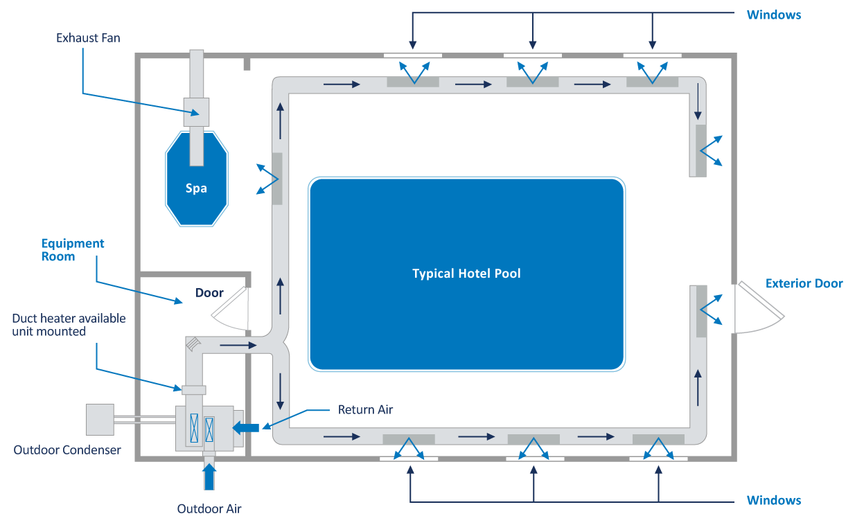
HOTEL AND RESIDENTIAL MARKET
Hotel and residential pools are typically smaller with light usage compared to institutional pools. Besides the pool water heating option, they tend to select unit designs without some of the other heat recovery options that are usually incorporated into larger units:
- This configuration is usually refrigeration based with the outdoor ventilation air connected directly to a special intake at the unit.
- The space heating coil is also mounted internally.
- The exhaust fan is usually installed in the space with its intake over the hot tub.
- The air conditioning heat rejection is to a remote outdoor air-cooled condenser.
The configuration in Figure 12 is very popular in hotel and residential applications because of their compact footprint and limited service access requirements.
There are a multitude of other configurations available should a horizontal unit or outdoor packaged system better suit the project. The heat rejection can also connected to a geothermal loop, dry cooler, or cooling tower.
FIGURE 12: SLB CABINET
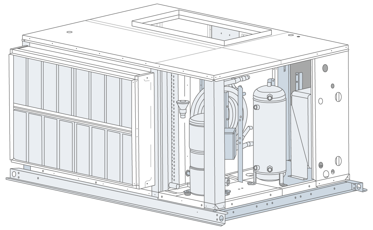
FIGURE 13: TYPICAL HOTEL AND THERAPY POOL LAYOUT
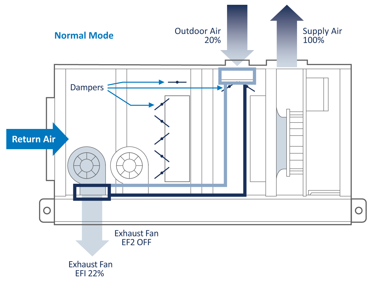
PURGE-ECONOMIZER LAYOUT
This configuration is popular in larger systems that are looking for flexibility with outdoor air amounts. These systems are designed with multiple dedicated duty exhaust fans. The first exhaust fan (EF1) is sized to maintain the room’s negative pressure by exhausting 10% more room air than is introduced to the space as code-mandated ventilation outdoor air. The second exhaust fan (EF2) is sized to allow up to full purge/evacuation of the space with a 100% outdoor air mode.
Figure 14 displays a unit in “Normal Operation” where EF1 maintains the room’s negative pressure. EF1 can be unit mounted or remotely installed with its intake located above the whirlpool whenever appropriate.
EF2 is normally off and operates only when a purge or economizer demand exists.
FIGURE 14: NORMAL MODE
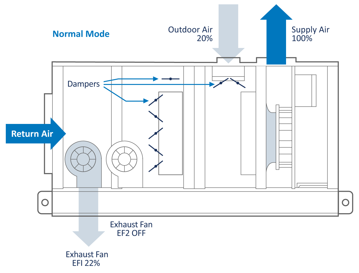
The outdoor air intake is set to introduce the code-required ventilation outdoor air (aka minimum OA) until the system goes into Purge-Economizer mode when it opens to 100%.
These minimum outdoor air and EF1 air streams at vastly different conditions present a perfect opportunity for heat recovery. The heat recovery coils could easily be introduced into the air streams of this unit configuration. This approach to heat recovery offers the best performance and design flexibility while staying in the smallest possible cabinet. Figure 15 displays a unit in “Normal Operation” with the glycol heat recovery coils in place.
FIGURE 15: NORMAL MODE WITH GLYCOL HEAT RECOVERY
If the system design has remote exhaust fans, the glycol runaround loop can still be used for heat recovery.
A significant added benefit to heat recovery is the tempering of the outdoor air before it can mix with the system air. Tempered outdoor air will not create condensation problems during the cold weather. In cold climates, it is very common to add a separate heating coil for the outdoor air if heat recovery is not being utilized.
Figure 16 displays a unit in “Purge-Economizer mode.” There are four significant benefits to this configuration:
FIGURE 16: PURGE-ECONOMIZER MODE
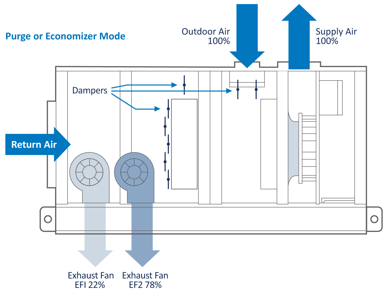
1. 100% air purge capability available at any time. The operator can super-chlorinate the space with 100% outdoor air to quickly clear out any airborne chemicals.
2. It also allows for a means to deliver a complete air change of the space should it require a quick purge.
3. Built-in economizer operation. All controls and mechanical equipment are already in place to operate in economizer cooling and dehumidification modes whenever the outdoor air conditions are suitable. This offers the operator the most economical year-round system operation.
4. This configuration consumes significantly less energy than traditional supply/return fan economizer systems with a mixing box because of the specific duty exhaust fans. They only operate when required compared to the supply and return fan configuration that has both full-sized fans operating year round. EF1 is a very small horsepower fan. EF2 operates only when called upon or when the outdoor conditions are suitable for economizer operation whereas the traditional approach has two full-sized fans operating year round.
These system features can be designed into the ductwork or incorporated into the unit as a complete package.
TABLE 6 – EXHAUST FAN OPERATION
| EXHAUST FAN OPERATING SEQUENCE EXAMPLE | |||
|---|---|---|---|
| Exhaust Fan EF1 | Exhaust Fan EF2 | Outdoor Air | |
| Normal Operation | ON | OFF | Minimum required by code |
| Purge–Economizer Mode | ON | ON | 100% |
EVACUATOR INTEGRATION
From an HVAC standpoint, the Evacuator is an exhaust fan that just factors into the total exhaust air required for the space. They generally exhaust the same amount of air needed to keep the space negative, so they blend into the design nicely. There are several ways to set things up with Evacuators:
- Evacuators are totally stand alone.
– Simply reduce the CFM of EF1 in the unit accordingly.
- Provide a dedicated air path, the EF1, and use the dehumidifier’s exhaust fan.
- Provide the dedicated air path, EF1, and a heat recovery coil.
- Provide a heat recovery coil in the dehumidifier for outside air preheat, and a remote heat recovery coil gets installed at the Evacuator exhaust air.
The Evacuator control strategy is either constant air volume (CAV) or variable based on a VOC meter. The dehumidifier should be set up to modulate outside air in concert with the Evacuator exhaust.
Chapter NINE
There are tens of thousands of existing dehumidification systems in operation today, many at their end of their useful life and in need of replacement. For example, an R22 system in operation today is very expensive to keep running, making it a prime candidate for replacement.
EVALUATING THE EXISTING SYSTEM
There is a tendency to simply replace the dehumidifier for the same exact unit. While that is certainly an option, this is really the time to assess the site and evaluate how the existing system performed and if it met the owner’s expectations. What was state of the art 15-20 years ago is very different to what is considered best practice today.
A complete audit is recommended. The pool might be used completely differently to its intended original design. Treat the audit as a new pool project and re-evaluate owner expectations. Once those expectations are established, shortcomings of the system can be considered for remediation.
- What are the desired operating conditions?
- Is the existing air distribution sufficient? Upgrading the ducting can be cost prohibitive, but sometimes a few changes to the existing system could dramatically improve air delivery in general.
- Does the system meet today’s codes?
- Is there adequate exhaust air? Could the Evacuator help improve the air quality?
- How is the building envelope holding up? Professional assessment is likely needed. If there has been any degradation, this could lead to an envelope failure.
- Have any water features or toys been added? These are very popular, and it is quite possible some have been added.
- Where can energy be saved?
EQUIPMENT OPTIONS
The size and accessibility of the mechanical room will likely determine which equipment is ultimately selected. Manufacturers offer many different unit configurations in a variety of footprints:
- Smaller units are designed to fit through a standard 32” door.
- Stackable units. Multiple smaller units that fit through a door are simply stacked once in the mechanical space and can provide a simple solution to midsized pools.
- Splitable units. While there are limitations, units can be “sliced” and reassembled once in the mechanical room.
- Refurbishing or rebuilding of existing equipment. If the cabinet is still in good condition, units can be “gutted” and reverse engineered to fit into the existing cabinet.
Chapter ten
In order to ensure the system performs reliably and that the equipment is suitable for an indoor pool environment, there are several features that must be included.
FLUID COOLED DESIGN
Refrigerant charges must be kept at a minimum. As refrigerants get phased down/out, costs increase. The phasing out of R22 refrigerant, for example, has made these systems very expensive to run.
Fluid cooled units typically reduce the system charge by 50-60%. An industry-leading unit can enhance efficiency by reducing refrigerant charges by as much as 80-90%.
Due to the operational requirements of the compressorized dehumidifier, they are very different to an air conditioner and have very large refrigeration charges. Attaining lifetime equipment support may also pose a challenge as service technicians seldom encounter these units on a regular basis.
Simplifying the refrigeration circuit and reducing the overall complexity results in a system that is easier to service and is also more environmentally friendly. Less refrigerant equates to less liability and exposure to unnecessary service costs.
MICROPROCESSOR CONTROL
The dehumidification system controls the entire natatorium environment. It needs to operate reliably and be easy to support.
Consequently, a control system that is tried and proven is in the best interests of the facility.
An operator will get much better support over the life of the system when people are familiar with the equipment. A proper microprocessor controller has a full range of unit-mounted sensors, pressure transducers, and remote sensors that can all be accessed from the keypad, building management system interface, or over the Internet. All necessary information regarding the system operation and conditions in the space should always be at the fingertips of the operator and support team.
INTERNET CONNECTION
Web monitoring redefines the concept of factory service and support by remotely monitoring, analyzing, and reporting all the critical functions of the dehumidifier – in real time via the Internet. All necessary information regarding unit operation can be viewed from any web-enabled device. Setpoints can be adjusted, sensors can be recalibrated, and unit performance can be monitored.
Unit alarms will generate emails to any email address on the pool owner’s contact list. Contractors who install or service the equipment can be set up to access the units. The facility owner, especially those in remote locations, will have a more efficient means of ensuring their units are monitored and service is supervised by factory technicians.
Factory certified service companies offer pool operators 24-hour monitoring, a new standard in customer satisfaction and unit reliability.
REFRIGERANT PRESSURE TRANSDUCERS
Unit-mounted pressure transducers allow the operator or service technician to access the vital refrigerant pressures through the operator panel of the microprocessor (or remotely via the Internet) rather than having to connect a set of refrigerant manifold gauges. This is the most important operation and diagnostic information for any refrigeration system, and the ability to access this information at any time is a significant benefit. Systems without refrigerant pressure transducers require a service technician to physically visit the site and connect gauges when information regarding the refrigeration circuit operation is desired.
The refrigeration pressure information from these transducers is used in the control of the dehumidifier. The operational history of the operating pressures is also stored in the controller. This provides access to critical historical information for diagnostics and trouble shooting. A system without refrigerant pressure transduces is considerably more costly and difficult to service over its lifetime.
EXHAUST AIR HEAT RECOVERY
The exhaust air is energy rich and can be used to preheat the incoming outdoor air. Heat recovery has an immediate and significant return on investment, even in milder climates. The reason for this is the exhausted air is warmer than traditional rooms and has relative humidity levels typically between 50-60%.
A glycol runaround loop approach is recommended because it is service friendly and has the best annualized performance.
There are software tools available to provide an ROI analysis to help illustrate the savings from this option.
POOL WATER HEATING
This option satisfies ASHRAE Energy Standard 90.1 and can contribute considerable operating cost savings.
The pool water heat exchanger should be either potable water rated cupronickel or titanium.
As with exhaust air heat recovery, there are software tools available to provide an ROI analysis to help illustrate the savings from this option.
RECEIVER REFRIGERANT LEVEL INDICATORS
Sight glasses mounted on the receiver allow for easy refrigerant charge adjustment without the expense of evacuation and weigh-in techniques.
DIRECT DRIVE PLENUM FANS WITH VFD
Direct drive ECM and plenum fans with VFD offer the most efficient means of moving air while using the lowest possible fan energy. Belt-driven systems are antiquated and a maintenance concern. They can also consume as much as 25% more fan energy. ECM fans and VFDs allow for easy supply air balancing without changing pulleys or belts.
COATED AIRSIDE COILS
All coils exposed to the pool air must be corrosion protected. It is best practice for all coils to be fully dipped to ensure the entire coil is protected from corrosion. Coil coatings should also have hydrophilic properties to allow the condensate on the evaporator to drain more efficiently.
COMMISSIONING AND STARTUP
The startup must be performed by an experienced and qualified professional. If the startup is not being carried out by a factory technician, it should be performed by someone who regularly and routinely starts up these systems. The best unit in the world will not operate to expectations if not started up correctly. The final performance review and adjustment of a dehumidifier can only be completed once the natatorium is operating at design conditions. Often, the initial startup is done with a cold pool; however, all facilities require a follow-up visit once the water has reached design conditions. It is highly recommended that a factory technician perform the startup to ensure optimal performance.
Chapter ELEVEN
The designer should address the following issues to ensure the unit is properly installed and can be serviced and maintained.
ACCESS SPACE
Access to a unit must be safe. If a technician cannot safely and comfortable access a unit, it cannot be optimally serviced.
No Access = No Service or Maintenance.
Refer to factory submittal drawings for recommended clearances.
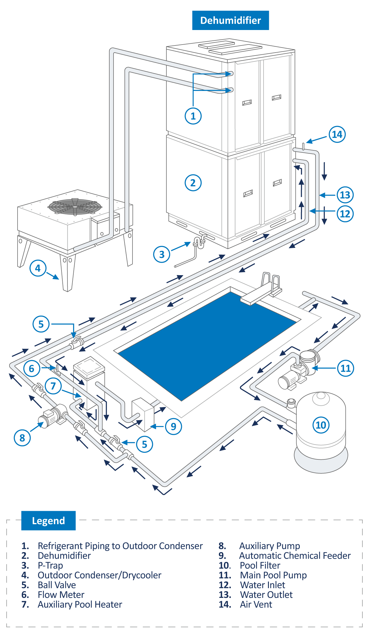
POOL WATER HEATING (OPTION)
This option can contribute considerable energy savings over the life of the system. A quick calculation of the annual energy savings can help establish the return on investment. This option is simple to design into the pool water circuit.
- The water circuit should tap off the main pool water line downstream of the main filter and upstream of the auxiliary pool water heater and chemical feeder (see Figure 17).
- An auxiliary water pump to deliver the unit’s required water flow rate is required. This is an open system, and the pool’s main circulating pump can rarely accommodate additional system pressure.
OUTDOOR AIR COOLED DRY COOLER OR CONDENSER INSTALLATION
This heat exchanger is used in air conditioning mode where it rejects unneeded heat from the space to outdoors. Proper installation is essential to ensure it functions as intended. Proper airflow and refrigerant piping are paramount.
- Ensure an appropriate maximum ambient air temperature has been specified.
- Ensure the unit has proper airflow and that the discharged air from the fan can escape fully; otherwise, operational problems will result. A perimeter of free area equal to its width must be provided as well as a means for the air off the unit to dissipate.
- Use line sizes as specified by the manufacturer.
- To avoid potential seasonal system charge problems with outdoor condensers, ensure the installed line lengths are never longer than indicated on the plans and specifications.
- If the condenser is installed above the dehumidifier, ensure the hot gas line has proper oil traps.
- Contact the manufacturer if the condenser is to be installed more than 50 feet away or eight feet below the dehumidifier. There are some absolute limitations that cannot be exceeded without jeopardizing system reliability and operation.
- Specify the lines be nitrogen purged while being brazed to help avoid scaling inside the pipe.
- All the refrigeration requirements disappear when using fluid-cooled systems or dry cooler systems!
FIGURE 17: RECOMMENDED ACCESS SPACE